A TEXAS REGULATOR'S GUIDE
to the
HIGH PERFORMANCE BIOFILTRATION/DRIP IRRIGATION ON-SITE WATER RECLAMATION SYSTEM
by David Venhuizen, P.E.
INTRODUCTION
Over the last 15 or so years, there have been a number of reports in the literature on the performance of modified recirculating sand filter systems. Besides providing the excellent removal of organics, solids and bacteria for which sand filters have been renowned for over 100 years, these particular systems also proved capable of removing a majority of the nitrogen from household wastewater by clever manipulation of the nitrogen cycle. A thorough review of this background is provided in High Performance Biofiltration: Where Sand Filters Have Gone on this web site.
Building upon the knowledge gained from those studies and drawing upon his own experience with sand filter technology, in 1990 David Venhuizen proposed the use of this denitrifying sand filter concept as a solution to wastewater management problems on Washington Island, Wisconsin. Wisconsin regulators required Washington Island to install and monitor demonstration systems to confirm whether the state's groundwater quality standards could be met by this system on sites with poor soil resources.
Of particular concern on Washington Island were thin soils over fractured bedrock. Washington Island's water supply comes from a karst, dolomitic aquifer which is highly vulnerable to pollution. Nitrate pollution was of particular concern, since nitrate-nitrogen can persist even where soil depth and quality are adequate to fully treat septic tank effluent in all other regards. Nitrates can readily migrate to bedrock, then "mainline" through fissures into the aquifer with no further treatment. A very similar situation to this exists in the recharge and contributing zones of the Edwards Aquifer in Central Texas. Other Texas aquifers and its coastal waters are also vulnerable to nitrate pollution.
Before proceeding, it must be stressed that a denitrifying sand filter system (or any other system practical for use in the on-site environment) cannot totally eliminate nitrogen or bacteria from wastewater. An effective soil dispersal system is still needed to complete the water reclamation process. Exploring means by which the effectiveness of minimal soil resources can be maximized was an integral part of the Washington Island project.
Intensive monitoring of system performance, conducted by the University of Wisconsin-Green Bay, was carried out over a two-year period in 1992-94. Venhuizen analyzed the results of the demonstration project and submitted reports to the state detailing and interpreting the data, and proposing design criteria. After thorough review, Wisconsin regulators agreed that these systems would meet groundwater standards on sites with thin soils overlying fractured bedrock. (On its technical merits, in 1995 Wisconsin briefly permitted the high performance biofiltration system for use on sites with limited soil resources. Then politics of land use took control of the process and it wasn't until 2000, with the adoption of a new statewide code, that it was possible to permit more systems.)
Having built upon the best ideas developed by previous efforts, the Washington Island experience provides a sound basis for the standardized high performance biofiltration treatment system designs developed by Venhuizen. Knowledge he gained by hands-on participation in that project is bolstered by many years of study in this field and over 10 years of experience in designing, installing, operating, maintaining and monitoring sand filter/drip irrigation systems in Central Texas.
This guide reviews how the Washington Island systems were built and how they performed. The lessons learned are applied to generate a high performance biofiltration system design that provides high quality treatment, relatively "fail-safe" operation, and fairly cost efficient construction. Dispersal of system effluent to accomplish effective irrigation reuse is discussed, and design of drip irrigation systems to disperse the effluent is delineated. Potential maintenance needs are noted and suggested procedures are detailed. Review of this document will provide a regulatory agency with adequate knowledge to address the permitting process for this technology. Having been proven capable of providing environmentally sound wastewater management on sites with even severely limited soil resources, this is a valuable management strategy for many areas of Texas.
THE WASHINGTON ISLAND PROJECT TREATMENT SYSTEMS
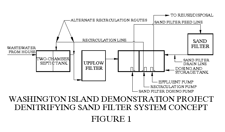
All prior studies of denitrifying sand filter technology had employed some form of attached-growth anoxic reactor in the treatment train, usually a horizontal flow or upflow rock bed filter. This type of reactor was generally thought to be necessary to achieve a high degree of denitrification. Adhering to this expectation, the Washington Island treatment systems consisted of a septic tank, anaerobic upflow filter and intermittent sand filter in series. Sand filter effluent was recirculated, directly into the upflow filter in one trial, and into the second chamber of a two-chamber septic tank in all other systems. A pumped recirculation scheme was employed. This treatment system concept is illustrated in Figure 1.
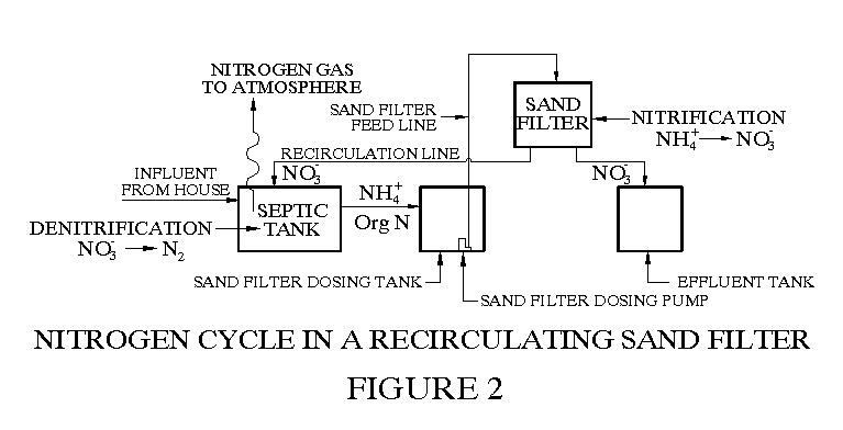
The nitrogen cycle in this recirculating sand filter system is shown in Figure 2. Nitrogen removal is achieved by first converting the ammonium nitrogen in septic tank effluent to nitrate nitrogen-a process called nitrification-which occurs as a matter of course in the biofiltration process, then routing this nitrified effluent into an environment rich in organic material and devoid of oxygen. Both these requirements are met by the septic tank and the upflow filter. These are necessary conditions for denitrification-the conversion by bacteria of nitrate into nitrogen gas. This bubbles off into the atmosphere, 80% of which is already nitrogen gas. So this type of recirculation scheme is a relatively simple means of eliminating the majority of the nitrogen from wastewater.
Physical characteristics of the seven demonstration systems installed on Washington Island are shown in the following table. The Foster and Njord Heim systems served seasonal users and generated limited data. Performance of the other five systems is summarized in Tables 1-10. Organics and solids removal are displayed in Tables 1-5, and nitrogen removal is detailed in Tables 6-10. General conclusions are that effluent BOD5 and TSS will average well below 20 mg/L and that about 60-90% of total nitrogen will be removed. Percentage removal appears to increase with influent total nitrogen concentration, and effluent total nitrogen levels averaging about 15 mg/L should typically be expected. Not shown in the tables, project results also indicated that effluent fecal coliform counts on the order of 102-104 CFU/100 mL can be expected, a level of performance usually observed in sand filters. This represents a 99-99.99% reduction from levels typically found in septic tank effluent.
WASHINGTON ISLAND DEMONSTRATION WASTEWATER SYSTEMS PHYSICAL CHARACTERISTICS AND DESIGN PARAMETERS
|
Design
|
Septic tank volume
|
Septic tank
|
Upflow filter
|
Upflow filter
|
Sand filter
|
Sand filter design
|
||
|
|
flow rate |
1st ch. |
2nd ch. |
design HRT |
volume |
design HRT |
bed area |
loading rate |
|
Johnson system: |
||||||||
|
|
300 |
500 |
500 |
40/40 |
245 |
19.6 |
30.25 |
9.9 |
|
Briesemeister system: |
||||||||
|
|
250 |
425 |
343 |
43/32 |
135 |
13.0 |
25.0 |
10.0 |
|
Boniface system: |
||||||||
|
|
300 |
584 |
559 |
47/45 |
193 |
15.4 |
30.0 |
10.0 |
|
Foster system: (First septic tank chamber is pre-existing holding tank) |
||||||||
|
|
300 |
2,000 |
456 |
160/36 |
136 |
11.0 |
30.0 |
10.0 |
|
Njord Heim system: |
||||||||
|
|
150 |
304 |
225 |
49/36 |
65 |
10.5 |
25.0 |
6.0 |
|
Mann Store system: |
||||||||
|
|
300 |
584 |
559 |
47/45 |
193 |
15.4 |
30.0 |
10.0 |
|
Richter system: (Main house has pre-existing S.T. of unknown volume, cottage has 505 gal. 1st ch. S.T.) |
||||||||
|
|
360 |
— |
464 |
??/31 |
193 |
13.0 |
36.0 |
10.0 |
FILTER BED MEDIA:
| Johnson system: |
|
Through December 1993 -- stratified bed design |
| Top layer -- 12" fine gravel (approx. 1/4"-3/8", 6-9.5 mm) |
| Bottom layer -- 12" coarse sand (effective size approx. 1.5 mm) |
| December 1993 thru end of data period -- 24" fine gravel (approx. 1/4", 6 mm) |
| Briesemeister system: |
| 24" coarse sand (effective size approx. 1.5 mm) |
| Boniface system: |
| 28" fine gravel (approx. 1/4"-3/8", 6-9.5 mm) |
| Foster system: |
| 24" coarse sand (effective size approx. 1.5 mm) |
| Njord Heim system: |
| 24" coarse sand (effective size approx. 1.5 mm) |
| Mann Store system: |
| Stratified bed design |
| Top layer -- 12" fine gravel (approx. 1/4"-3/8", 6-9.5 mm) |
| Bottom layer -- 12" coarse sand (effective size approx. 1.5 mm) |
| Richter system: |
| 24" coarse sand (effective size approx. 1.5 mm) |
|
Click here to see the BOD/TSS data tables. Click here to see the Nitrogen data tables. |
THE LESSONS LEARNED
Much was learned from observation of the Washington Island systems. A lesson with great practical implications is that, when loading conditions are optimized, little-if any-organics and solids removal efficiency would be lost by using even a very coarse filter media. Indeed, others have learned and applied this lesson, and recirculating gravel filters have been used nationwide. Typically a media of about 2-3 mm effective size has been used. The 6-9.5 mm gravel used in the Boniface system is very coarse relative to this, yet this system still consistently produced superior effluent.
The major benefit of using coarser media is reduced maintenance liabilities. Since some of the solids in wastewater are non-degradable, any wastewater filter will eventually become so highly laden with solids that cleaning of the filter will be required. In sand filters employing finer media, the problem is mainly confined to surface clogging, but in coarse media biofilters, solids will penetrate more deeply into the bed and a greater amount of solids can be stored in the filter bed without causing severe clogging. How fast the buildup of solids proceeds to the point where it compromises performance depends upon how well clarified wastewater is before it is applied to the filter and upon the quantity of solids which can be stored in the bed before excessive clogging or pass-through of solids occurs. Using coarser media should increase maintenance intervals, all other things being equal. The expected interval between bed cleanings for the standardized system detailed later in this paper is 5 years or more.
Another very significant observation was that high nitrogen removal can be achieved without an attached-growth anoxic reactor in the system. (Rich Piluk in Anne Arundel County, Maryland-a National Onsite Demonstration Project site where denitrifying sand filters were also used-had in fact shown this to be true a couple years before.) Tables 6-10 show that, in most cases, even the small second septic tank chambers in the Washington Island systems by themselves provided sufficient denitrification potential that there was little left for the upflow filter to do. The upflow filters in some of these systems clogged near the end of the monitoring period, indicating that eliminating this component would decrease system maintenance liabilities, assuming of course that measures are taken to compensate for the BOD5 and TSS reductions that would have been provided by the upflow filter.
It has been said that one often learns more from failure than from success. The truth behind this maxim was well illustrated by experiences with the Johnson system and the Briesemeister system. A recirculation pump failure in the Johnson system highlighted the benefits of recirculation for general system function as well as for nitrogen removal. Along with the failure of the Briesemeister system to perform adequately as a single-pass system during the 11 months it was operated in that mode, this experience also underscores the need for frequent dosing of filters containing coarser media. Almost immediately upon installation of a recirculation system, which enforced a loading cycle consisting of frequent small doses, the Briesemeister system began to exhibit exemplary performance, even though the system was overloaded through most of the following summer.
Severe spray head clogging in the Johnson system showed how critical uniform distribution over the filter surface is to good performance, which confirms that a spray system covering the entire bed surface is the preferred method of influent distribution. The clogging occurred due to a design flaw-which had already been identified and eliminated from the other system designs-and it persisted for months because of regulatory problems regarding proper procedures for tank entry to repair the problem.
This circumstance was fortuitous in a way. By the time that the spray loop was reworked to correct the flaw, the filter bed was highly compromised. Even so, a quick and dramatic improvement in system function was observed after uniform distribution was re-established. This fast recovery illustrates the resiliency of sand filter technology. That the problem could be circumvented altogether by insightful design hints at how even a fairly high-rate biofiltration system can be designed and built so as to incur minimal maintenance liabilities.
The Washington Island systems proved to be quite stable, even in the face of highly variable loads. Each spring, the Richter system experienced no performance degradation when the residents began loading the system after an extended vacation. The Mann Store system, which received a very high strength influent stream to begin with, coasted through periods of extremely high organics and solids loading each summer with minimal degradation of removal efficiency, although the effluent BOD5 concentration did run a little above 30 mg/L. "Recovery" to extremely high quality occurred quickly after the end of the peak tourist season, which dictates the annual cycle of wastewater flow from this store. And, as noted previously, the Briesemeister system accommodated excessive loading for over two months without any apparent degradation in system performance.
The Washington Island systems were designed with a quite "aggressive" 10 gallons/ft2/day forward flow hydraulic loading rate onto the sand filter. Over much of the observation period, however, occupancy patterns in the homes served by these systems resulted in somewhat lower actual loading rates. Only the Briesemeister system operated for an extended period at or above 10 gallons/ft2/day.
Both the Johnson and Briesemeister systems produced consistently high quality effluent over extended periods of operation at loading rates in the range of 7 gallons/ft2/day or greater. The Briesemeister system had a 1.5 mm sand media, and the Johnson system had a stratified media bed consisting of 6-9.5 mm gravel overlying 1.5 mm sand. The Boniface system, employing that very coarse gravel media mentioned previously, exhibited consistently excellent performance over the monitoring period at an average forward flow loading rate of 3.4 gallons/ft2/day, but with average septic tank effluent BOD5 and TSS concentrations of 316 mg/L and 160 mg/L, respectively. At more typical septic tank effluent concentrations of 120-150 mg/L BOD5 and 60-80 mg/L TSS, a loading rate of over 7 gallons/ft2/day would have been required to produce equivalent organic and solids loadings on the system. For the Mann Store system, which employed the same stratified media as the Johnson system, it would have taken a huge 12.5 gallons/ft2/day flow rate at 150 mg/L to obtain the equivalent organic load produced by the high strength inputs at lower flow rates.
These observations, combined with results of several other efforts in this field, inspire confidence that-when the system concept is optimized-operation at around 7 gallons/ft2/day could endure indefinitely without resulting in significant maintenance liabilities, when treating domestic wastewater. As detailed later, this information is used to size the filter bed in the standardized system.
EVOLUTION OF THE SYSTEM CONCEPT
Pretreatment Modifications
Results of the Washington Island project indicated how system design could be improved. First, it was observed that the primary septic tank chamber was undersized and/or not optimally configured in most of the systems, resulting in the fairly high-strength inputs to the sand filter system just noted. This situation is remedied in the standardized high performance biofiltration system.As pointed out previously, the upflow filter is eliminated from the system, and denitrification will be obtained by recirculating through either a primary or secondary septic tank, where high organic loads would assure anoxic conditions and provide an adequate energy source for the denitrifiers. This strategy could, however, worsen the problem of high BOD5 and TSS concentrations in septic tank effluent, due to the higher flow rate through the septic tank imposed by the recirculation flow.
To counter this problem, an effluent filter is installed on the outlet of the septic tank. If multiple septic tank chambers are used, an effluent filter would be installed at the outlet of each chamber. Effluent filters of the type made by Zabel and Orenco have been shown to consistently provide significant reductions in BOD5 and TSS concentrations in septic tank effluent. These devices would not just prevent increases in septic tank effluent strength that might be caused by recirculation flow, but they would also achieve to some degree the reductions in BOD5 and TSS previously afforded by the upflow filter. While effluent filters also require maintenance, it appears that they would need to be cleaned rather infrequently if properly sized. Even in the unlikely event that they require cleaning more often than the recommended frequency of once every year or two, this is a very simple and easy maintenance procedure relative to the effort and equipment required to backflush an upflow filter.
The standardized design also employs an "oversized" septic tank volume, whether a single-chamber primary tank or both a primary and a secondary chamber is used. Sedimentation theory indicates that, given the low average flow velocity through this tank even with recirculation flow added, settling efficiency is highly dependent upon length of flow path. Therefore, a larger (longer) single chamber should provide better sedimentation performance than two chambers with an equivalent total path length, due the "dispersal and gathering" effects at the inlets and outlets, which retard settling efficiency. Two-chambered designs are favored by most codes because this design attenuates wash through of solids caused by flow surges. In the standardized design, the effluent filter on the outlet fulfills this purpose. So a larger septic tank fitted with an effective effluent filter will consistently produce a more highly clarified effluent. Obviously, this is more critical when a single-chamber primary tank receives the recirculation flow. It is recommended that, for home-sized systems, a septic tank volume equal to 3.5-4.0 times the daily design forward flow (HRT of 84-96 hours) be used in this situation, with required HRT decreasing as design flow rate increases. (A tradeoff between volume in the primary tank and volume in a secondary septic/recirculation chamber, if used, can also be considered, so long as the total HRT in the two tanks remains at or above 84-96 hours for a home-sized system.)
A larger primary chamber is also favored for maintenance economy. Better retention of solids in the primary chamber implies faster sludge buildup, which may increase required pumping frequency. This impact is again blunted by using an oversized septic tank, which provides more volume for sludge buildup without prematurely "closing down" the sludge clear space.
A single-chamber oversized primary tank will provide increased contact time for recirculated effluent, which will enhance denitrification potential. If both a primary and secondary chamber are used, with recirculation flowing only through the secondary chamber, it is likewise oversized to provide increased contact time. Based upon observations in the Washington Island systems and similar efforts, a secondary chamber with a volume equal to at least the daily design forward flow (HRT of at least 24 hours) should be used in home-sized systems to assure practically complete denitrification.
The standardized design takes further precautions to reduce solids loading onto the filter bed by incorporating an in-line filter on the outlet of the filter bed dosing pump. The type of unit employed in the standardized design described in this paper provides filtration down to 600 microns (1/50th of an inch). This will not only minimize maintenance liabilities due to clogging of the filter bed, it is also expected to enhance filter bed efficiency. Recent work by Dr. George Tchobanoglous and others at the University of California at Davis indicates that reducing average particle size in wastewater loaded onto a biofilter bed will increase treatment efficiency. The in-line filter unit used in the standardized design will assure that only smaller particles are loaded onto the filter bed.
Improved Gravity Recirculation Scheme
The other major alteration in system configuration is discarding the pumped recirculation system in favor of a gravity recirculation scheme. A pumped recirculation scheme as used in the Washington Island systems can guarantee the required uniform dosing pattern, which gravity recirculation schemes commonly employed in on-site sand filter systems cannot. However, the vulnerability of the pumped recirculation scheme was highlighted by the pump failure in the Johnson system, which went unnoticed for a month and a half even in a system that was being monitored twice weekly. There is no ready way to install an alarm to warn of recirculation pump failure; operation of this pump must periodically be visually verified. So it was determined to find a way to dispense with this pump.
The most common way to implement gravity recirculation is to use a split filter bed, with one side draining to the recirculation loop and the other flowing to the effluent tank. The filter bed dosing pump is controlled by a timer and the dosing tank serves as an equalization basin, filling up during periods of high water use and being drawn down during periods of low flow from the house. This arrangement is illustrated in Figure 3. It can be shown that when actual flow is somewhat below design flow rate, there would be "gaps" in the dosing cycle, through much of the night and perhaps through the afternoon as well, unless the dosing cycle is adjusted to match the actual flow through the system on each day. The impracticality of continuously matching filter dosing rate to actual forward flow is obvious.
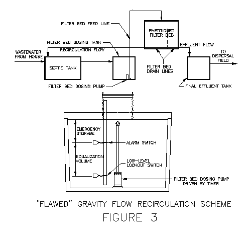
Since statutory design flow rates are typically rather liberal, long-term average flow rates are quite often below the design flow rate, so this problem of non-optimal dosing patterns is likely to be very common. Further, during extended periods of no flow from the house, as when the occupants go on vacation, dosing of the filter bed would cease completely, and the system would have to "cold start" when flow resumed.
This situation can be readily corrected. When flow from the house is low, flow that would otherwise have gone to the effluent tank is routed back into the dosing tank, using the scheme illustrated in Figure 4. When this occurs, the entire volume of water dosed onto the filter bed eventually flows back into the dosing tank, some of it indirectly through the recirculation loop as it always does, and the rest directly from the "effluent side" of the filter. This scheme assures that the dosing tank could never run out of water and the filter bed dosing cycle would not be interrupted, no matter how little flow issued from the house.
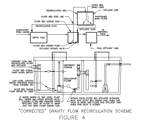
This method is implemented by using an "effluent bypass valve". The valve opens when the filter bed dosing tank water depth drops below a pre-set level. This allows drainage from the "effluent side" of the filter bed to drop into the dosing tank instead of overflowing into the effluent tank. When flow from the house is sufficient to keep the dosing tank supplied, this valve remains closed and drainage from the "effluent side" of the filter bed flows into the effluent tank.
The bypass valve is a highly reliable standard product, providing a fairly fool-proof means of assuring that the filter bed is always dosed at intervals called for by the design theory. As detailed later, the system design incorporates precautions which accommodate short-term failure of this valve and an alarm that will sound if the valve fails to open when it should. Application of proper system maintenance procedures would assure proper performance over the long term.
Standardized High Performance Biofiltration System
The system concept that has evolved from these observations and discoveries is illustrated in Figure 5. A timer-driven filter bed dosing pump and the effluent bypass valve assure that the filter bed is loaded with the same hydraulic load on the same schedule every day, regardless of the volume of flow coming from the house. The organic strength of the water dosed onto the filter bed will vary, depending on how much flow recirculates through the effluent bypass valve (and also on the strength of the wastewater coming from the house, of course). Regardless of these organic strength variations, steady-state hydraulic loading of frequent small doses will allow the filter bed to perform at maximum efficiency, readily accommodating variable organic strength with minimal impact on performance.
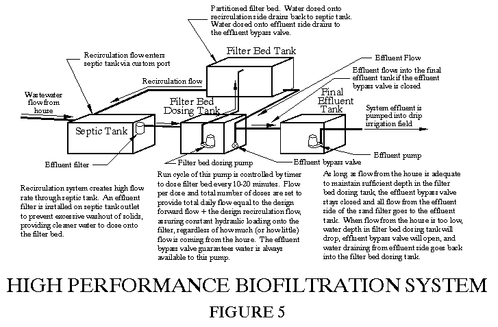
Using this concept, the system's design recirculation ratio is set by the ratio of flow onto the two sides of the filter bed. Based upon results of the Washington Island project and other studies of this technology, it was concluded that a 2:1 ratio on the design flow rate is a good compromise. Using this ratio, total hydraulic load-the sum of forward flow plus recirculation flow-onto the filter bed is moderate, and good nitrogen removal performance is typically obtained.
This recirculation ratio is implemented by installing 4 spray heads on the "recirculation side" and 2 heads on the "effluent side" in a home-sized filter bed. Each head contains the same kind of spray nozzle and system piping is arranged to minimize difference in head loss to each nozzle, so nozzle flow rates will be very uniform. Therefore, 2/3 of every dose will flow to the recirculation loop and 1/3 will flow to the effluent tank-a 2:1 recirculation ratio. This corresponds to a recirculation rate of 3:1, meaning that for every gallon of forward flow, three gallons are loaded onto the filter bed, the other two gallons being recirculation flow.
When forward flow is below the design rate, the filter bed dosing sump will be drawn down and the effluent bypass valve will open, so additional flow would be recirculated through the filter bed (without increasing flow through the septic tank) to make up for the deficit in forward flow. As noted, this additional recirculation dilutes the strength of wastewater dosed onto the filter bed, which will do nothing but improve system effluent quality.
In practice, the dosing system would be set up to provide more recirculation flow. A typical recirculation rate is 3.5:1 for residential systems (3.5 gallons loaded onto the filter bed for every gallon of design forward flow). This will draw down water level in the dosing tank and cause the effluent bypass valve to open and close at least once during the diurnal cycle even when the full design flow rate is being produced in the house, diluting the strength of filter bed influent as noted. Again, this will improve filter bed treatment efficiency.
One final "wrinkle" is incorporated into the system concept. The split filter bed separates filter bed effluent into two distinct flow streams. It was quickly realized that, since it just flows back through the septic tank, the quality of flow out of the "recirculation side" of the filter bed can be allowed to degrade slightly. A 30 mg/L BOD5 concentration would serve just as well as a 10 mg/L level, as long as significant nitrification was achieved. Therefore, rather than using a filter bed surface area ratio of 2:1 and loading both sides at the same hydraulic loading rate, the "recirculation side" area can be reduced, increasing the loading rate on this side, and the "effluent side" enlarged, resulting in a lower loading rate onto it. This will enhance quality of the "effluent side" drainage and slightly degrade quality in the recirculation loop. A further refinement would be to use different media in the two sides of the filter bed. A larger media can be used in the "recirculation side" to reduce clogging potential at the higher loading rate, and a finer media can be used in the "effluent side" to enhance final effluent quality even more.
Filter Bed Design Loading Rates
As noted previously, results of the Washington Island project (and also of several other investigations of sand filter technology-see again "High Performance Biofiltration: Where Sand Filters Have Gone") indicate that an average forward flow loading rate of 7 gallons/ft2/day or more (for normal household wastewater) can be supported. The design criteria chosen for the standardized system "push" this to a limit of about 8 gallons/ft2/day on the "recirculation side" and "relax" it to about 5.5 gallons/ft2/day on the "effluent side". With a 3.5:1 recirculation rate on the design flow rate, these forward flow loading rates dictate a total hydraulic loading rate onto the "recirculation side" of about 29.75 gallons/ft2/day and onto the "effluent side" of about 19.25 gallons/ft2/day. Long term total hydraulic loading rates in excess of these were supported by the Washington Island systems, with excellent performance resulting, as indicated in Tables 1-5 and Tables 6-10.
STANDARDIZED SYSTEM COMPONENTS
Components of the high performance biofiltration system can be standardized, so that the system can be produced and provided "off-the-shelf" similar to other packaged treatment units. This will simplify installation and better assure uniform quality, so that the regulatory agency can have a high degree of confidence that the system concept is faithfully executed. Regardless of whether the system is implemented with such components or is custom assembled at the project site, system components must conform to sizing and performance standards dictated by the concept. This section reviews tank configurations and other system components to be used to implement the standardized high performance biofiltration system. Component design is illustrated with calculations for a "prototype" tank set. Tanks from any manufacturer could also be similarly justified for the design flow accommodated by each product.
Septic/Recirculation Tanks
Figure 6 shows how a standard single-chamber septic tank is modified to serve as a septic/recirculation tank for the high performance biofiltration concept. Risers and hatch covers provide a secure seal and convenient access for cleaning the effluent filter, checking sludge level, and pumping the tank. The risers can be integrally cast into a customized tank lid, or they can be attached to the tank deck at the project site, taking measures to assure a watertight seal between the riser and tank lid. A non-standard port for entry of the recirculation flow into the septic tank can be cast in by the tank manufacturer, or the recirculation drain pipe can connect to the building drain at any convenient point in front of the septic tank. These features allow local manufacturer's standard tanks to be used without any field modifications in their construction.
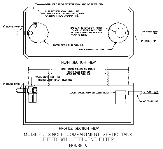
The Zabel A100 is specified as the effluent filter on Figure 6. Orenco's 6" Biotube filter may also be used, but the 4" model is too small to accommodate the proposed recirculation flow rates without requiring frequent cleaning. Either the Zabel A100 or the 6" Biotube is expected to provide adequate clarification of septic tank effluent.
With a sizing criterion of at least 3.5 times the daily design flow rate (84 hours HRT) for single-chamber primary septic/recirculation tanks, a design flow rate of 360 gpd would be accommodated by a 1,250-gallon tank, and a design flow rate of 420 gpd would be accommodated by a 1,500-gallon tank. Most tank makers have standard products up to this size. As noted previously, HRT should increase with decreasing design flow rate. It is suggested that a 1,250-gallon tank also be used for a 300 gpd system and that a 1,000-gallon tank be used for a 240 gpd system, providing at least 96 hours HRT in each case.
For design flow rates higher than 420 gpd, it is expected that two tanks in series would be a more cost efficient installation. If this configuration is used, recirculation flow is typically routed through the secondary chamber only. This reduces flow through the primary chamber and settling efficiency in that chamber would be better, so the primary chamber need not be oversized as much as if it were the only septic tank chamber. In this case, total septic tank volume should still be at least 3.5 times the daily design flow rate (84 hours HRT), with at least 1.0 times that rate (24 hours HRT) as the secondary chamber volume. Without recirculation flow going through it, a 4" Orenco Biotube effluent filter could be used on the outlet of the primary chamber in this configuration, while either the 6" Biotube or the Zabel A100 is required on the secondary chamber outlet.
Pump Tank
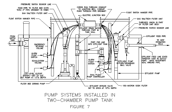
When used as a pump tank, various tank makers' standard septic tanks will accommodate different maximum design flow rates. Sizing calculations for a "prototype" tank system accommodating a design flow rate up to 360 gpd are detailed in this section. For design flow rates in excess of those accommodated by two-chamber tanks in the size range typically produced by tank makers, separate tanks could be used for the filter bed dosing tank and the effluent tank. The following reviews the system installed in a two-chamber pump tank.
Displayed in Figure 7 is the configuration of a two-chamber pump tank, housing the filter bed dosing chamber and the effluent chamber. Appropriately sized standard two-chamber septic tanks provide the basic configuration shown in the figure. A non-standard port must be added to the side wall of the tank for entry of the drain line from the "effluent side" of the filter bed. Also, a non-standard port in the cross-wall for the drain pipe into the effluent chamber is typically required, as it must be higher than most standard septic tank cross wall ports. Otherwise, the only modification from standard construction is again customization of the lid. Risers with secure lids are added to allow ready access to pumps and filters for maintenance, and an inspection port over the entry tee on the septic tank drain line is installed. As for the septic tank, the risers can be integrally cast into a customized tank lid, or they can be attached to the tank deck at the project site, taking measures to assure a watertight seal between the riser and tank lid.
The dosing chamber must contain a permanent liquid depth to protect the pumps from overheating, the equalization volume, and the emergency storage volume to allow time to replace a failed pump when the high water alarm sounds, signaling failure of the dosing pump. By design, the permanent liquid depth is set at 15 inches to assure most of the pump is covered at all times. (Note that the pump is set on a block, as explained below.) The emergency storage volume is set equal to the design daily flow rate, in theory allowing up to 24 hours to replace a failed pump.
The filter bed dosing tank equalization volume-the amount of water between the depth at which the effluent bypass valve opens and the depth at which the high water warning alarm goes off-must be sufficient to minimize the likelihood of "false alarms". These occur when a high flow surge-such as when the residents host a large party-consumes the equalization volume and drives water level up to the alarm even though the dosing pump is working as required. It has been observed in similar types of systems being extensively used in Anne Arundel County, Maryland, that 2/3 of the design daily flow is sufficient for this purpose. A suggested criterion for the standardized design is a minimum of 75% of the design daily flow for home-sized systems.
If "false alarms" occur frequently, this alerts the user to routinely excessive water use-a leaking toilet, for example. The user should correct this problem as soon as practical to prevent long-term hydraulic overloading of the system. Being quickly alerted to such problems could also save the user a considerable amount on the water bill. This alarm may also be a real indication that the pump has failed, which is, of course, its main purpose. The larger the equalization volume as a percent of design daily flow rate, the lower the probability of "false alarms" being a nuisance, but making this volume too large allows high flow conditions to go undetected for longer periods of time. The calculations justifying dosing chamber sizing of a "prototype" tank for a 360 gpd system are shown below. The regulatory agency should require similar calculations to be submitted to justify the tank actually proposed for the design flow rate of the system in question.
DOSING CHAMBER SIZINGTo accommodate up to 360 gpd design flow rate = 48.12 ft3
Dosing tank chamber - 68"x72" bottom dimensionsInterior depth of tank is 45" 2" taper in 45"
0.0444" taper per inch of depth
Permanent liquid depth = 15" = bottom of equalization volume
Area at 15" depth = [68+(2x0.667)] x [72+(2x0.667)] = 5083.97 in2 = 35.31 ft2Assume top of emergency storage at 44" (accounting for lid shiplap)
Area at 44" depth = [68+(2x1.96)] x [72+(2x1.96)] = 5460.1664 in2 = 37.92 ft2Neglecting taper, required emergency storage depth = 48.12/37.92 = 1.27' = 15.2" Allow 16.5"
Area at 27.5" depth = [68+(2x1.22)] x [72+(2x1.22)] = 5243.5536 in2 = 36.41 ft2Emergency storage volume = (36.41+37.92)/2 x 16.5/12 = 51.10 ft3 = 382 gal > 360 gal -- OK
Equalization volume = (35.31+36.41)/2 x (27.5-15)/12 = 37.35 ft3 = 279 gal = 78% of 360 gal -- OK
The effluent chamber must contain a minimum permanent liquid depth for pump cooling, the emergency storage volume, and the dose volume-the amount of water routed to the irrigation system at any one time. By design, the permanent liquid depth is set at 15 inches, and again the emergency storage volume is equal to the design daily flow rate. As will be detailed later, the drip irrigation field should function best when dosed more frequently with small doses, yet there would be a minimum dose size required to assure uniform distribution throughout the drip hose array. As detailed in the section on drip irrigation, the minimum dose volume expected to be required for a 360 gpd system is 66 gallons. (Note: The dose size justified here is for a pump system operating under volumetric control-that is, a given volume of water is pumped to the field whenever it builds up in the tank. A timer controlled system would typically require a greater storage volume in the effluent chamber. That situation is not addressed here.)
The calculations below justify the effluent chamber size in the "prototype" tank for a system design flow rate of 360 gpd. The regulatory agency should require similar calculations to be submitted to justify the tank actually proposed for the design flow rate of the system in question.
EFFLUENT CHAMBER SIZINGTo accommodate up to 360 gpd design flow rate = 48.12 ft3
Effluent tank chamber - 68"x51" bottom dimensionsInterior depth of tank is 45" 2" taper in 45"
Permanent liquid depth = 15" = bottom of dose volume
Area at 15" depth = [68+(2x0.667)] x [51+(2x0.667)] = 3628.0389 in2 = 25.19 ft2Area at 44" depth = [68+(2x1.96)] x [51+(2x1.96)] = 3952.0432 in2 = 27.44 ft2
Emergency storage, neglecting taper - 48.12/27.44 = 1.75' = 21"Allow 22"
Area at 22" depth = [68+(2x0.98)] x [51+(2x0.98)] = 3705.0816 in2 = 25.73 ft2Emergency storage volume = (25.73+27.44)/2 x 22/12 = 48.74 ft3 = 365 gal > 360 gal -- OK
Allow 1/2" for alarm switch above dose top
Area at 21.5" depth = [68+(2x0.96)] x [51+(2x0.96)] = 3700.1664 in2 = 25.70 ft2
Available for dose - (25.19+25.70)/2 x (21.5-15)/12 = 13.78 ft3 = 103 gal > 66 gal -- OK
Filter Bed Dosing Pump System
The discharge line of the dosing pump is fitted with a GAG Sim/Tech filter unit to provide a final level of pre-filtration before water is loaded onto the filter bed. This filter has a fine mesh screen which supports a 600-micron filter sock. As discussed previously, this will reduce the potential for clogging of the filter and will reduce particle size of solids that do flow to the filter bed. A pressure switch connected to the filter body by a sensor tube is wired to the control panel. This switch will trigger an alarm when the sock becomes sufficiently clogged to increase the pressure loss through it to a preset point (typically about 2 psi above the clean sock pressure). When this alarm goes off, the sock should be cleaned or replaced, as outlined in the section of this paper on maintenance procedures. (Note: Similar in-line filters, such as a "spin-clean" Y-strainer, may also be used instead of a Sim/Tech filter. However, none of them are designed to incorporate a pressure switch, although one could be retrofitted into the system.)
As shown in Figure 7, the dosing pump is set on a block to elevate it above the floor of the dosing chamber. Since solids are "blocked" by the Sim/Tech filter, they will be retained in the dosing tank, and they will wash down the discharge pipe when the pump turns off and then settle on the bottom of the dosing chamber. Elevating the pump off the floor allows some buildup of solids on the floor without sucking them back into the pump each time it turns on. This should decrease the frequency at which the Sim/Tech filter sock needs to be cleaned.
The filter bed dosing pump and Sim/Tech filter are connected to the filter bed feed line with a threaded union that is part of the filter body. This allows the pump to be easily disconnected and reconnected when service is required. The filter bed feed line exits through a pipe grommet or port in the hatch riser and runs over the tank deck. This eliminates the need to further modify the tank to provide a port for this line. Since the filter bed containment tank must be placed above this tank so it can drain to it and to the septic/recirculation tank, the feed line can be routed so that it will completely drain back between doses. This will minimize slime growths within this pipe and consequent potential for spray nozzle clogging.
Effluent Bypass Valve
Various types of devices can be used for the effluent bypass valve. Illustrated in Figure 8 is the Robert Manufacturing valve, which is commonly used to control water level in stock watering tanks. Thus, this valve has a long history of reliable use with normal waterline pressure behind it. In the present application, the valve will have no more than a few feet of head behind it. The "S" riser pipe on the valve outlet is installed to minimize the possibility of debris lodging on the valve seat and compromising the seal. Water level in the dosing tank will only be above the outlet of the "S" riser when the valve is closed, so there can be no backflow of dirty water to the valve. This "S" riser is not glued onto the threaded adapter on the valve outlet so that the riser can be removed from the slip connection when the valve is rotated a quarter turn. Then the entire valve can be completely unscrewed from the drop pipe if it ever needs servicing or replacement. Similar valves of this type may be designed with the valve seat above the water line to preclude that liability. A captive ball valve may also be used, but these are typically somewhat more expensive. However, the performance history of that type of valve indicates that fouling is not expected to be a problem.
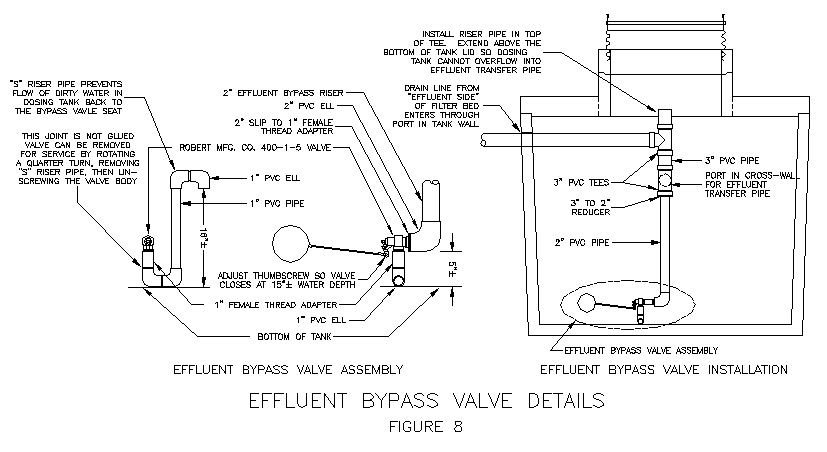
The control system is designed for the worst case, the possibility of the effluent bypass valve malfunctioning. As noted previously, the dosing cycle is typically set up to force this valve to operate every day, minimizing the likelihood that it would seize up. However, if the valve seizes up in the closed position, the system would operate under the "flawed" gravity recirculation scheme shown in Figure 3. When somewhat less than the design flow rate issues from the house, the dosing tank would frequently run out of water, as detailed previously. As shown in Figure 7, a low-level cutoff switch, set an inch or so below the level at which the effluent bypass valve is supposed to open, prevents the dosing pump from running "dry" if the bypass valve fails to open and water level in the dosing chamber continues to drop. If water level does drop to the low-level cutoff switch, an alarm will sound, alerting the user that the effluent bypass valve has malfunctioned.
In the unlikely event that the valve seizes up in the open position, all flow would drop into the dosing tank rather than flow into the effluent tank. This, of course, will cause the dosing tank water level to rise as long as there is forward flow into the system. The water level could rise to the level of the effluent bypass line overflow pipe into the effluent tank. At this point, water from the dosing tank could backflow through the valve into the effluent tank, bypassing the treatment process. The system is designed so that the high water alarm would trip below this overflow level. If, upon checking the alarm condition, the dosing pump is found to be working properly, the maintenance technician will know to check the bypass valve. Therefore, the system should not operate at or above the overflow level for a significant amount of time before the problem is corrected.
The effluent pipe is extended into the effluent chamber to near the edge of the hatch opening. There it is capped with a tee, from which is hung a sock filter. The filter sock is 150-micron material, similar to the 600-micron sock installed in the Sim/Tech filter unit. This sock filter will minimize the impact of any backflow through the effluent bypass valve that might occur if the valve seized up in the open position. It will also intercept secondary regrowth solids that may build up and slough off of the filter bed drain pipe walls.
Irrigation Water (System Effluent) Pump System
The drip irrigation field may be pressurized directly by the effluent pump, or indirectly by using a hydropneumatic system, in which case the pump is started and stopped by a pressure switch. The latter is a more complex setup and is not discussed in this paper.
The effluent pump must supply the high head needed in the drip irrigation field. The effluent feed pipe to the field typically exits the pump tank through an outlet port that is located about where the standard outlet port of a septic tank would be. There is a ball valve installed on the discharge line that serves to allow the field feed line to drain back to the effluent chamber when the pump turns off. This will minimize the potential for slime growth in the feed pipe. It also creates a bypass that can be used to adjust field head and to assure that the pump does not "deadhead" if the feed line were to become blocked for any reason.
The effluent pump is also fitted with a GAG Sim/Tech filter unit with a 600-micron sock filter installed in it. While the biofiltration treatment process will typically deliver highly clarified effluent, this water still contains some organics and nutrients. Experience has shown that there may be some secondary regrowth on effluent tank walls and on the pump and piping. These growths may become suspended in the water and be sucked into the pump. The Sim/Tech filter prevents these solids from being routed to the drip irrigation field. Because there is a 100-micron screen filter at all drip line entries, the Sim/Tech filter is actually redundant protection, but its presence should increase required cleaning intervals for drip field strainer screens. Again, the threaded union on the Sim/Tech filter unit provides for easy disconnection and reconnection of the effluent pump when it needs to be pulled for service. Just as for the dosing pump Sim/Tech filter, a pressure switch connected to the filter body by a sensor tube is wired to the control panel.
Pump Control System
The pump control system is illustrated in Figure 9. The dosing pump is started and stopped by a repeat cycle timer. This device activates the pump for a precise amount of time on constant intervals. Power from the timer runs to a junction box next to the hatch riser. The power feed wires may be connected to a plug-in outlet, allowing the pump cord to be simply unplugged rather than dewired if the pump must be replaced. This eliminates the need to do any field wiring when the pump is replaced. As noted previously, a low-level cutoff switch wired into the control panel protects the pump against burnout in case the effluent bypass valve seizes up in the closed position. The high water alarm for the dosing pump is also wired into the control panel.
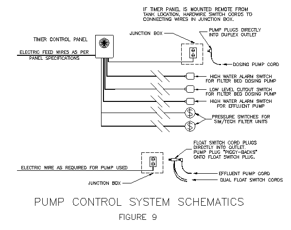
The Sim/Tech filter pressure switches for both the dosing pump and the effluent pump are wired into one alarm in the control panel. It is presumed that if the user or a service provider goes out to clean one filter, it would be little additional effort to clean the other at the same time, so only one alarm is provided. A pressure switch installed on the Zabel filter in the septic/recirculation tank may also be connected to this alarm to signal when that filter requires cleaning. When the filter becomes sufficiently clogged, flow surges through the septic tank will cause water level to rise enough to trigger the pressure switch. While it is recommended that the Zabel filter be cleaned at 1-year intervals, this alarm can alert the user in case a particular system requires more frequent cleaning. If used, this would also be wired to the same alarm to which the Sim/Tech pressure switches are connected.
The instantaneous flow rate produced by the pump is determined by characteristics of the filter bed feed system. The pump is chosen to produce sufficient flow to drive the distribution system being used. As noted previously, spray distribution is used in the high-performance biofiltration concept. The pressure recommended to drive the spray head is obtained from the manufacturer, or from actual testing to achieve a desired spray pattern. This pressure plus friction losses in the feed piping and the elevation head between the dosing chamber water level and the filter bed spray loop determine head requirements of the pump. Because the losses in the feed and distribution system can vary, it is recommended that actual flow out of the spray heads be observed in the constructed system before setting up the actual dosing cycle in the field.
Once the dosing interval and the design recirculation rate are chosen, and the actual flow out of filter bed spray heads are measured, the dosing cycle can be established. The following provides an example of these calculations for a 360 gpd system. The regulatory agency should require similar calculations for the setup proposed for each system.
- Design flow rate = 360 gallons/day
- Design recirculation rate = 3.5
- Total daily flow onto filter bed = 3.5 x 360 = 1,260 gallons
- Dosing interval = 15 minutes
1440/15 = 96 doses/day
- Volume per dose = 1,260/96 = 13.1 gallons/dose
- Measured instantaneous flow rate to filter bed = 24 gallons/minute
- Dose time = 13.1/24 = 0.55 minutes = 33 seconds
To the dose time calculated in this manner must be added the time it takes to fill up the feed piping till water actually begins to flow onto the filter bed, since the system is designed so that the feed pipe will drain back between doses. Repeat cycle timers typically are set up with an "off" time and an "on" time. Assuming it takes 7 seconds to fill the feed piping, in this example the "on" time would be 33 + 7 = 40 seconds and the "off" time would be 15 minutes minus 40 seconds, or 14 minutes, 20 seconds to obtain doses at 15-minute intervals. Most practical timers cannot be set with such accuracy, so that the actual dosing cycle is typically a close approximation of the calculated values.
The effluent pump is controlled by a dual-float control switch, which affords very accurate dose sizing. The pump plug "piggy-backs" onto the switch plug, which plugs into an outlet wired onto the pump power feed wires. This plug is placed in a junction box next to the hatch riser. As shown on Figure 7, typically one junction box would be placed between the hatch over the dosing chamber and the hatch over the effluent chamber to house the outlets for both pumps, and to splice the float switch cords to feed wires from the control panel. The high water alarm for the effluent pump is wired into the control panel.
Filter Bed Containment Tanks
Illustrated in Figure 10 is the filter bed containment and feed system. This containment could be fabricated in a modified 2-chamber septic tank. As with the pump tanks, various manufacturers models will accommodate different design flow rates. The design flow rate for each tank model should be justified for the regulatory agency in a similar manner as shown below for a "prototype" tank design:
Filter Bed Sizing for 360 gpd system with 2:1 filter bed recirculation ratio:
Recirculation side - 360 x 2/3 = 240 gpd forward flow @ 8 gpd/ft2
Assume form used has 68" bottom width with 2" wall taper
30/5.833 = 5.14' = 62"
As Figure 10 illustrates, the influent distribution system consists of a pipe loop with spray nozzles dropping down from it. This allows the loop to drain through the nozzles after the pump shuts off, which will minimize slime growths in the pipe. This in turn decreases the potential for spray nozzle clogging. That was the problem with the Johnson system. In that system, the spray heads pointed up from the loop, so the pipe stayed full of septic tank effluent between doses, and slimes continually clogged the heads.
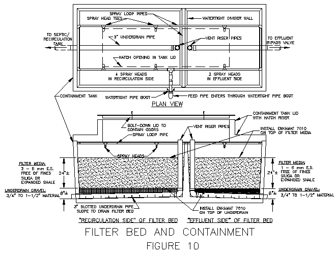
The spray nozzles used in the standardized design are manufactured by Bete Fog Nozzle, Inc. They produce a wide spray pattern, providing excellent coverage of the bed surface in the low headway available in the containment tank. Spray distribution in this manner satisfies the requirement for uniform distribution, a major design principle for the high performance biofiltration concept. The openings in these nozzles are fairly large, minimizing the potential for clogging. Each of the nozzles can be reached easily through one of the hatches in the tank lid. The nozzles, which have threaded connections, can be unscrewed and removed for cleaning, if required. Using this nozzle design, good coverage of home-sized filter beds is obtained by installing two spray heads over the effluent side of the filter and four over the recirculation side, obtaining the 2:1 design recirculation ratio noted previously.
The hatch openings also provide access to inspect and service the filter bed, the installation of which is also shown on Figure 10. A very coarse gravel underdrain promotes complete drainage of the filter media and aeration throughout the media depth. Recommended size of this gravel is 3/4" to 1-1/2", which will provide very good drainage. This underdrain layer is installed on a bottom that is modified to slope toward the underdrain header pipe, which is a slotted 3" PVC pipe running along the bottom slope. This pipe exits through a port that is either cast in or drilled or hammered out. The port is made watertight with grout once the pipe is run through.
Two layers of Enkamat (a nylon filament erosion control mat) are placed on top of the coarse underdrain rock before the media is installed. This forms a barrier which prevents mixing of the filter media with the underdrain rock during the filter bed cleaning process, which is explained in the maintenance section. The erosion control mat also prevents intrusion of filter media into the relatively large voids in the underdrain rock.
A vent riser comes up from the upstream end of the underdrain header pipe. This allows the filter bed to "breathe" through the drain pipes. Note that the tops of the vent risers run up above the bottom of the tank lid. If the filter bed were to clog badly, influent could pond very deeply on the top of the media. If this were to overflow into the vent riser pipe, it would circumvent the treatment process, bypassing directly to the septic tank and-most critically-to the effluent tank. With the vent riser pipes running above the bottom of the lid, influent could never flow into them. Water would drain back through the spray heads into the dosing tank before it could pond this high.
This provides a "fail-safe" design. Proper application of maintenance procedures would preclude this situation from ever developing, but if, through neglect, the bed did become so highly clogged, and thus deeply ponded, that a significant portion of the dose were to drain back to the dosing tank, this would eventually cause water level in the dosing tank to rise to the high water warning alarm. If the pump were found to be in working order when the alarm went off, the maintenance technician would know to check the condition of the sand filter.
A 24-inch depth of filter media is placed over the gravel underdrain. This media may be a washed river run gravel or any manner of "manufactured" media, such as expanded shale, that has been properly graded. Typical media size is in the range of 1/8" to 1/4" (3-6 mm) effective size, and it must be of highly uniform size. The media is covered with a layer of Enkamat to prevent "duning" of the media surface from spray impact, to maintain a flat filter bed surface.
The rock used for media is typically sold in bulk, so is transported to the construction site in a truck or trailer. Installation can usually be done with a front end loader. If the lid is already sealed on, a "gravel chute" can be constructed to dump media through the hatches with a loader, or a "bucket brigade" may be used to install media. Bagged rock or sand media may also be used, perhaps expediting transport and installation. Typically, the media will have some silt or dust in it that must be washed out. If this is washed into the effluent tank, that chamber must be cleaned out so this material does not get pumped to the drip irrigation system.
As noted, expanded shale media has also been successfully employed in high performance biofiltration systems. Recently, research by others has offered the option of using very different types of media in biofiltration systems, namely foam and textile media. The high performance biofiltration system will accommodate these alternative media beds, should they prove to be more effective and/or cost efficient. Since the filter bed containment is a separate module, these alternative media beds could readily be "plugged into" the system. The balance of the high performance system remains the same, as any biofiltration bed would have its performance optimized by the arrangement built into the standardized system described here.
DRIP IRRIGATION REUSE SYSTEM
An integral part of the Washington Island project was an analysis of the fate of effluent once it entered the soil, with the aim of generating a dispersal field design that would provide maximum treatment efficiency in whatever depth of soil was available. A report of the findings was subsequently published by the Wisconsin agency that regulates on-site systems there and was distributed to local regulators throughout Wisconsin and beyond. An updated version of that paper is available on this web site. (Click on the "Soil Treatment" button to see this paper.)
A thorough review of the assimilation/removal mechanisms operating in the soil system leads to the conclusion that, for all pollutants of concern, three factors can be controlled to make these mechanisms more effective:
- shallow dispersal in the biologically active soil horizons;
- low areal loading rates; that is, low flow per square foot of field; and
- uniform distribution over the field area with a dose/rest loading cycle.
Due to the severity of winters in Wisconsin, a modified at-grade low-pressure-dosed trench system was recommended as the least problematic way to enhance the impact of these factors there. This system is designed to emulate drip irrigation to some degree. In Texas, however, true drip irrigation hardware can be utilized, installed at a very shallow depth. The ability of drip irrigation systems to provide very uniform distribution and to provide a slow wetting of the soil allows a lightly loaded drip field to maximize the three factors noted. This renders drip irrigation dispersal of high quality effluent the most environmentally sound "drainfield" that is practically attainable, a critical factor when dealing with the severely limited soil resources which are common over many parts of Texas.
The value of drip irrigation dispersal goes beyond that, however. A drip irrigation system is also the most practical way to obtain effective beneficial reuse of the "waste" water resource in the on-site environment. By installing the drip irrigation field to serve landscaping that would have been irrigated in any case, this method can displace a considerable amount of potable water demand. The potential savings are anything but trivial. In a study of one small water supply district, it was determined that, among those customers who practiced a significant amount of irrigation, the available savings might be in the range of 40-70% of total water demand throughout the May to September peak irrigation season. In many areas of Texas, adequacy of water supply is a chronic-and growing-problem, and peak water use driven by irrigation demands is a large part of this problem. Routing "waste" water to true beneficial reuse in a drip irrigation system can help to address these problems.
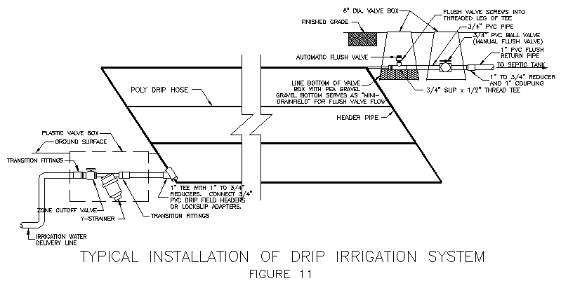
Since the effluent being routed to the drip irrigation system is highly clarified, a simple hardware system can be used. Figure 11 illustrates the drip field components. (Note: This figure shows the components required for a field being directly fed by the effluent pump. The hydropneumatic feed system mentioned previously would require additional components that will not be discussed in this paper.) A cutoff valve and a 100-micron strainer are installed at all drip hose entries, and a flush valve assembly is installed at the ends of the drip hose arrays. The automatic flush valve provides a "mini-flush" cycle each time the drip hose system is pressurized. The manual flush valve is opened to provide a scheduled maintenance flush of the hose array, as described in the section of this paper on system maintenance. A vacuum relief valve (not shown) allows the feed line to drain back between doses (to minimize slime growths in the feed pipe) without pulling a vacuum on the drip lines. That could suck soil water-and soil-into the drip emitters and lead to emitter clogging.
[A detailed design manual for drip irrigation systems is available on this web site. Click on the "Soil Treatment" button and select the Drip Irrigation Dispersal Design Manual.]
Based on water balance and nitrogen loading criteria, drip irrigation fields in Central Texas are sized in the range of 0.08-0.1 gallons/ft2/day. Under average year conditions, the field is, in terms of water balance, generally overloaded for about 4 months in the fall and winter, loaded about right for 2 months, and under-loaded the rest of the year. Design theory accepts that the drip field will act as a "drainfield" at times. This can occur at any time of the year, not just in the winter months, whenever antecedent moisture conditions are at field capacity-the degree of saturation at which deep percolation losses begin-when the irrigation feed pump comes on. However, over the annual cycle, the vast majority of effluent water will be lost through evapotranspiration rather than to deep percolation, minimizing the potential for transport of remaining pollutants to groundwater. During the hotter months, when the field may be not be receiving sufficient water to properly irrigate some of the plants, part of the field might be closed off to concentrate the available water on the most critical plants, or makeup water could be added to the effluent tank to satisfy the additional irrigation demands. The hydropneumatic feed system mentioned previously can incorporate an "automated" makeup water system.
To further enhance field efficiency for both beneficial reuse and soil treatment, the daily flow is loaded as a series of small doses, which limits the amount of effluent water injected into the soil at any one time. That minimizes the increase in soil moisture level caused by the effluent, in turn minimizing the potential for deep percolation losses. This is especially critical when antecedent moisture conditions are high. As noted, it is under these conditions that drip fields are most vulnerable to losing effluent water to deep percolation, so limiting the amount of effluent loaded at any one time enhances the environmental protection provided by drip irrigation systems.
Just as in low-pressure-dosed systems, drip systems require a minimum volume per dose to assure that a fairly uniform amount flows out of each emitter during each dose. In LPD systems, the typical standard is feed line volume plus five times the lateral pipe volume. Because, unlike an LPD system with its much larger orifices, very little flow will issue from drip emitters-which flow at about 1 gallon/hour-in the short time it takes the pipe system to fill up, it is suggested that a very safe criterion for minimum dose volume to assure highly uniform distribution in a drip field would be three times the drip hose volume. For a 360 gpd system with the field loaded at 0.1 gal/ft2/day, the drip field would contain no more than about 2,000 linear feet of drip hose. This would require about 22 gallons of water to fill up. Three times this is 66 gallons. As detailed previously, sufficient dose volume should be available in the effluent chamber of a 360 gpd system to accommodate this criterion, and to account for the volume of the feed pipe if it drains back to the effluent tank between doses.
OPERATIONS AND MAINTENANCE
While the standardized high performance biofiltration system described in this paper has been carefully designed to minimize maintenance liabilities, occasional attention will be required. In addition, periodic surveillance is strongly suggested as a way to head off the most troublesome operational problems. Suggested surveillance protocol and maintenance procedures are detailed in this section. This program has been found to be highly effective at keeping the systems operating "on track" in the Washington Island project and for on-site systems that have been operating for several years in Central Texas.
Arrangements for Surveillance and Maintenance
As an integral part of the design process, the owner would be provided with a manual that thoroughly details not only the surveillance protocol but the actual maintenance functions as well. This will assure that the owner-and any maintenance contractor the owner may hire-is well versed in the operational and maintenance needs of the system. It can be readily seen that these routine surveillance procedures could be easily executed by a motivated system owner. Obviously, however, there must be a mechanism for assuring that it is indeed done. This may take the form of requiring this activity to be executed by the regulatory agency or a third party maintenance entity, or of requiring the owner to fill out and submit a form reporting the results of each observation. Each regulatory agency must determine the policies which it feels will assure that an adequate surveillance program is in place, and that arrangements will indeed be made to accomplish any required maintenance activities. Statewide rules in Texas generally require maintenance contracts for systems of this design, but under certain circumstances, the system owner may be allowed to execute some or all of actions typically executed by a maintenance provider.
Periodic Routine Surveillance
All system functions should be checked periodically to verify that everything is working as required and to determine the need for executing the various maintenance procedures. This includes checking the dosing cycle of each pump, verifying that alarms work as required, observing drip field component condition and operation, and observing the condition of the filter bed. A suggested frequency for these observations is every 6 months, except for pump dosing cycle, for which checks every 12 months should suffice. On Washington Island, it has been found that each routine surveillance visit requires about 1/2 hour per system, more or less, depending upon whether any corrective actions are required at that time.
If the regulatory agency feels that a direct check on effluent quality is also needed, it is suggested that this could be executed quite expeditiously by taking a reading of filter bed effluent turbidity, which correlates well with effluent quality parameters. Tubidity can be easily checked in the field with a portable turbidimeter.
Checking filter bed dosing pump operation consists of observing whether the pump turns on and off when the timer "makes" and "breaks". Checking effluent pump operation consists of observing whether the pump turns on when the top float switch is level and turns off when the bottom float switch is level. High water alarms are checked by lifting their float switches to level and observing if the horn sounds and the light comes on. The low-level alarm is checked by depressing that float switch. It will probably be efficient to clean the Sim/Tech filters during the routine 6-month check if the pressure switch has not sounded prior to that time. If the pressure switch routinely goes off at shorter intervals, these filters must be cleaned at need. It may be most expeditious to carry spare socks and simply replace the filter sock, washing the dirty sock at the shop rather than in the field, or to just dispose of the dirty sock, since their cost is nominal.
In the drip field, operation of the flush valves is observed when the effluent pump comes on and starts to fill the drip lines. A small amount of water will be flushed out of these valves before the system pressurizes and causes them to seal. If they fail to seal, it is most likely due to debris being lodged in the valve seat. The valve can be readily disassembled, the debris removed, and the valve reinstalled. The condition of each strainer screen is observed by pulling the box cover, unscrewing the housing and removing the screen. The screen would be cleaned at the time of this inspection. Experience with each system will dictate whether these screens would need to be cleaned more frequently than once every 6 months. A "walkover" of the field area when the effluent pump is running will reveal any line breaks, which will be obvious because water will be coming to the surface at that point.
Condition of the filter bed is checked by opening the hatch covers. Each of the spray nozzles is checked for clogging while the dosing pump is running. The condition of the filter bed is observed at this time. If any water is ponded on the bed when the hatch is opened, or if water remains ponded on the surface for more than a minute or so after the dosing pump shuts off, this indicates that the bed is clogging to the point where maintenance is needed.
Septic Tank Maintenance
As with any on-site system, the septic tank will eventually require pumping. "Conventional wisdom" is that pumping frequency should be encouraged every three years. An analysis indicates that pumping frequency for the "oversized" septic tanks employed in the high performance biofiltration system could theoretically be 7 years or more. Recommended practice is to check sludge depth every year and pump when needed. The criterion for determining when the tank should be pumped is a 6-inch minimum sludge clear depth below the effluent filter inlet. This can be checked easily with a product called the "Sludge Judge" or with a light-colored rag wrapped around a dipstick, provided that the distance from the tank bottom to the effluent filter inlet is known. This is determined by the depth of the tank and the type of effluent filter used. The depth at which pumping is required would be recorded and stored at some convenient point for reference of the maintenance personnel.
Manufacturers recommend that effluent filters be washed off at least once every two years. However, the procedure is so easy to do that annual cleaning is suggested as a preventative maintenance procedure. The filter body can be easily pulled out of its housing through the hatch provided in the standardized design. It is simply hosed off, then reinserted into the housing.
Filter Bed Maintenance
Maintenance requirements for this component include spray nozzle cleaning and filter bed cleaning. To date, spray nozzle cleaning has been needed very infrequently. When it is needed, it has most often been due to leaves, etc., falling into the dosing tank and getting into the flow rather than to wastewater solids. When required, cleaning is easy to do. The spray nozzle is simply unscrewed so it can be removed and washed out, then it is screwed back into its fitting.
Because wastewater contains some solids that will not readily degrade, eventually the filter bed will clog. As noted previously, this should not be expected to occur for several years in a properly functioning system, but overloading or system malfunctions can lead to premature clogging. Whenever it occurs, even very severe clogging can be remediated in situ using standard, readily available equipment, thanks to an innovative procedure devised by Rich Piluk of the Anne Arundel County (Maryland) Health Department.
The procedure consists of plugging the filter bed drain line and flooding the filter, then "agitating" the bed with an air compressor, causing the wastewater solids to float out of the media. While the bed is being agitated, the water on top of the filter bed is sucked off with a pumper truck hose, carrying these solids away with it. A PVC pipe is attached to the compressor hose. The pipe is repeatedly inserted into the filter bed, agitating it rather violently. This is continued until water on top of the filter has been suctioned off down to the top of the media, then the water level is brought back up and the procedure is repeated. Execution of this procedure to date indicates that about five iterations will thoroughly clean the filter bed.
The cleaning operation can be completed working through the hatch openings in the standardized tank designs. The tank does not need to be uncovered and the tank lid does not need to be removed. No media needs to be removed and disposed of, and no new media needs to be hauled in and installed. Only liquid waste is hauled off, by a licensed septage hauler, and standard arrangements are in place for this.
Assuming that a compressor is delivered to the site for his use, the pumper truck operator could execute the entire process by himself, but a better procedure would be to have him assist a trained maintenance technician. If this cleaning can be done at the same time the tanks are pumped, the whole operation entails a fairly modest incremental cost. If the pumper truck has adequate capacity to do it all in one run, the filter bed can be cleaned, the septic tank can be pumped, and both pump tanks can be pumped and cleaned in about 3 hours or less. The major factor determining time requirement is how fast the filter bed can be refilled, which depends on the water system at the site.
Other Treatment System Maintenance
The only other maintenance which the treatment system may require is repair or replacement of pumps, valves, controllers, or alarms if they fail to function properly. When a pump malfunctions, it must generally be replaced within 24 hours, or the users must stop loading the system until it is, since an emergency storage volume equal to the daily design flow rate is provided by the standardized designs.
To replace a pump, it can be readily disconnected from the feed pipe by unscrewing the threaded union on the Sim/Tech filter body, then the pump and filter can be pulled out of the sump. The pressure sensor line must be disconnected from the Sim/Tech filter body. The electrical junction box is opened, the pump is unplugged, and the cord is threaded through the conduit. The riser pipe and Sim/Tech filter are unscrewed from the old pump and screwed into the new pump. The cord is threaded back through the conduit, the pump is plugged in, lowered into its sump, and reconnected using the threaded union. The pressure sensor line is reconnected to the Sim/Tech filter body. Since this entire process requires no special tools or skills, it could readily be executed by the system user if need be.
If the Robert Manufacturing effluent bypass valve seizes up, it can be unscrewed and removed once the "S" riser pipe is removed, as explained previously. The valve can then be serviced to restore free movement of the piston, or it can be replaced. The repaired or new valve is screwed back into the fitting, the "S" riser pipe is reattached, and the assembly is rotated into the operating position. Again, the replacement process requires no special tools or skills, and it could be readily executed by the system user.
If alarms fail to function, the problem may be in the switch or in the control panel. The float switches can be replaced by unstrapping them from the float switch hanger pipe and strapping on the new switch in the same position. The dual-float controller for the effluent pump has a plug-in connection, so it can be replaced without disturbing any hard-wired connections. Other switches would need to be dewired from and rewired to feed wires in the junction box. Likewise, the pressure switches, located in the junction box, would have to be dewired and rewired to replace them. Unless the user is well versed in electric wiring, this should only be done by qualified technicians. If any other control panel malfunctions occur, it is likely that these could only be addressed by qualified technicians or by the panel vendor.
Drip Irrigation System Maintenance
Maintenance of the drip irrigation system includes cleaning the strainer screens, flushing the drip lines, and injecting cleaning agents into the drip hoses, if required. As noted previously, the screens in the Y-strainers should be inspected-and will most likely require cleaning-at least every 6 months. This is done by pulling the cover of the box containing the strainer and unscrewing the strainer housing. The strainer screen can then be pulled out of the housing so its condition can be observed. If it requires cleaning, this is accomplished by spraying the screen from the outside with a strong stream of water. If the screens are highly clogged, they may need to be immersed in hydrogen peroxide. In the worst case, the screens can simply be replaced. It may be most expeditious to carry spare screens and simply replace the screen in the field and conduct the washing in the shop.
If water does not come out of an automatic flush valve for a few seconds before the drip hose array fully pressurizes, the valve is clogged and must be disassembled and cleaned, or replaced if required. The valve is threaded and easily unscrews to disassemble for cleaning. Observing automatic flush valve operation will indicate whether significant debris has accumulated in the drip lines. This is most often due to slimes building up on and sloughing off of the pipe walls. (Note that the Geoflow brand of drip irrigation hose incorporates a bactericide into the inner hose wall, which minimizes this problem.)
If debris is visible in the water that flushes out of these valves, this indicates that the drip hose needs to be flushed. It is recommended that this be done at least once every two years as a preventative measure in any case. Flushing is accomplished by opening the manual flush valves one at a time and allowing effluent to run through the drip hose feeding to that flush valve. The field pressure is converted to a higher flow rate, since the pump operates at a point on its performance curve with lower head and higher flow. This supplies a sufficiently high flow to assure good flushing action in all parts of the hose array. (A minimum flow velocity of 1 ft/sec is suggested by Geoflow.) The strainer screens should be cleaned prior to flushing so that head loss through them would be minimized. This procedure is repeated until all parts of the drip hose array have been flushed.
Once per year, the time it takes to evacuate a dose from the effluent tank should be observed and compared to the initial reading, which should be noted shortly after system startup and stored at some convenient location for reference of the maintenance personnel. This dosing time must be done after the screens are cleaned to assure that increased dosing time is not due to increased head loss through the screens. If the time it takes to evacuate a dose is more than 20% greater than the initial reading, this indicates that either chemical or biological clogging of the drip emitters has proceeded to the point that maintenance is recommended.
Chemical clogging is due to dissolved solids being deposited in the emitter when residual water left in the emitter evaporates between doses. It is addressed by injecting acid into the drip hoses. Since drip lines are buried and the system is designed to deliver multiple doses every day, it is not likely that water will evaporate from inside the emitters most of the time, so buildup of these deposits is not generally expected. Therefore, standard procedure would be to first dose the system with chlorine or hydrogen peroxide to remove biological clogging.
The injection of acid, chlorine or hydrogen peroxide solutions is done through the automatic flush valve fitting. The sector of drip hose being serviced is closed off by shutting the cutoff valve. The automatic flush valve is removed and a hose thread adapter is screwed into its fitting. The solution being injected is run through a hose hooked to this fitting. An expeditious method is to mix up the solution in a tank and use a pump to inject it into the drip hose array. The volume of solution must at least be sufficient to fully fill the drip hose so that the solution would be run to all parts of the drip hose array in the sector being serviced.
IN CLOSING ...
The high performance biofiltration system "packages up" and purveys a fairly cost efficient wastewater management method which has proven to be highly effective and reliable. It has undergone a testing program far more rigorous than the NSF Standard 40 procedure-it has been through trial-by-fire in the field. Mating the high performance biofiltration concept with a drip irrigation field, a system is created which minimizes environmental liabilities and maximizes beneficial reuse. Innovative design features are incorporated to maximize the efficiency of the method and to minimize operational and maintenance liabilities. The use of this method is encouraged wherever lack of sufficient soil resources creates a concern about threats to the environment and public health from on-site wastewater systems, or anywhere that beneficial reuse of wastewater is good public policy. As can readily be seen ...